2.4. Airfoil feature and modification
2.4.1. Geometric features
The FoilGeoFeatures class
provides functions to extract geometric features from the airfoil data.
Geometric features:
Leading edge radius
Volume
Thickness line
Camber line
Curvature
Maximum thickness
Thickness at 20% chord and 70% chord
Maximum camber
Average camber
Weighted average camber
Average camber of front 60% and rear 40%
Leading edge slope angle
Trailing edge wedge angle
Trailing edge slope angle
Upper crest point
Lower crest point
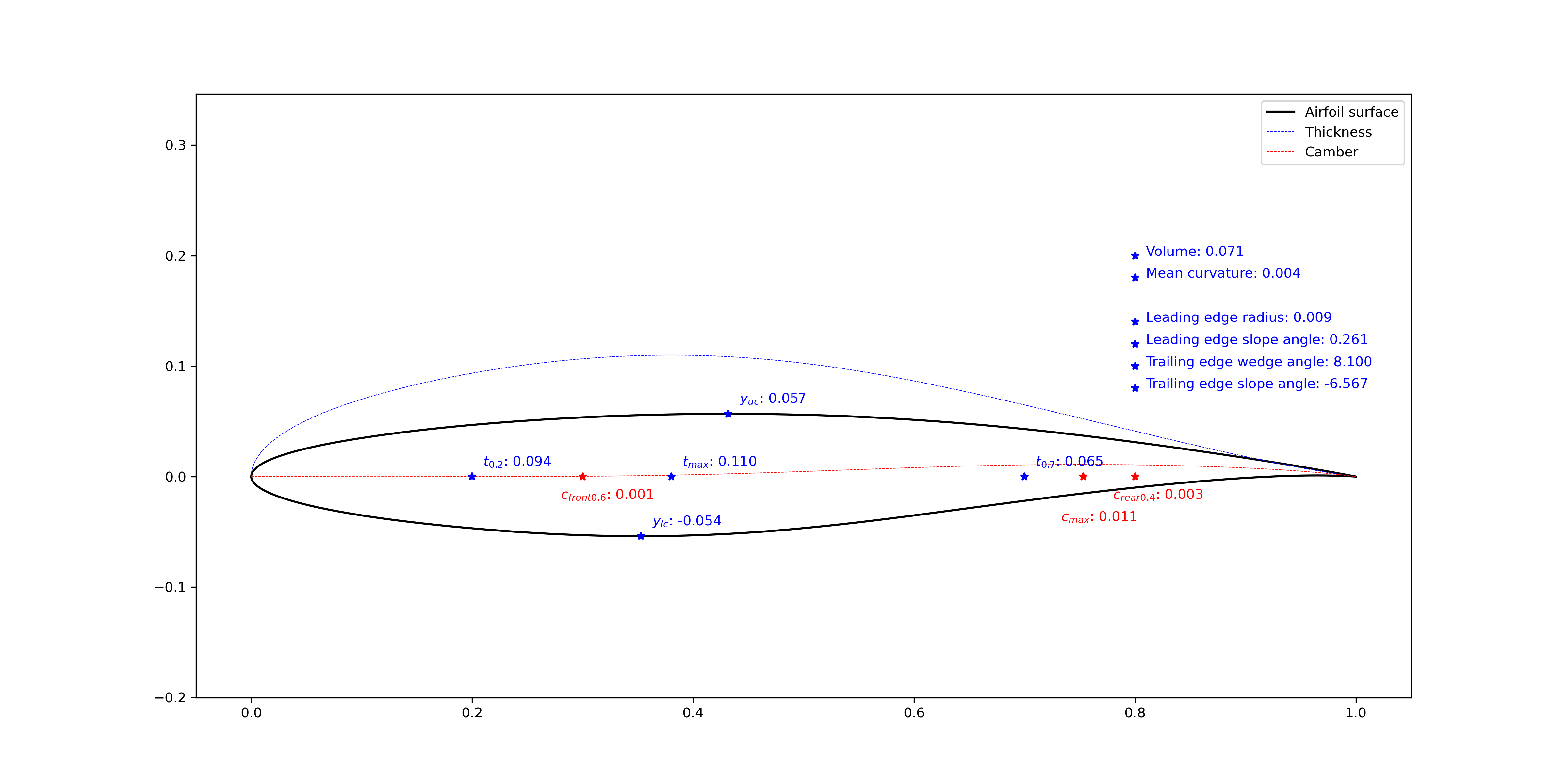
Figure 2.4.1 Airfoil geometric features (tail=0.000)
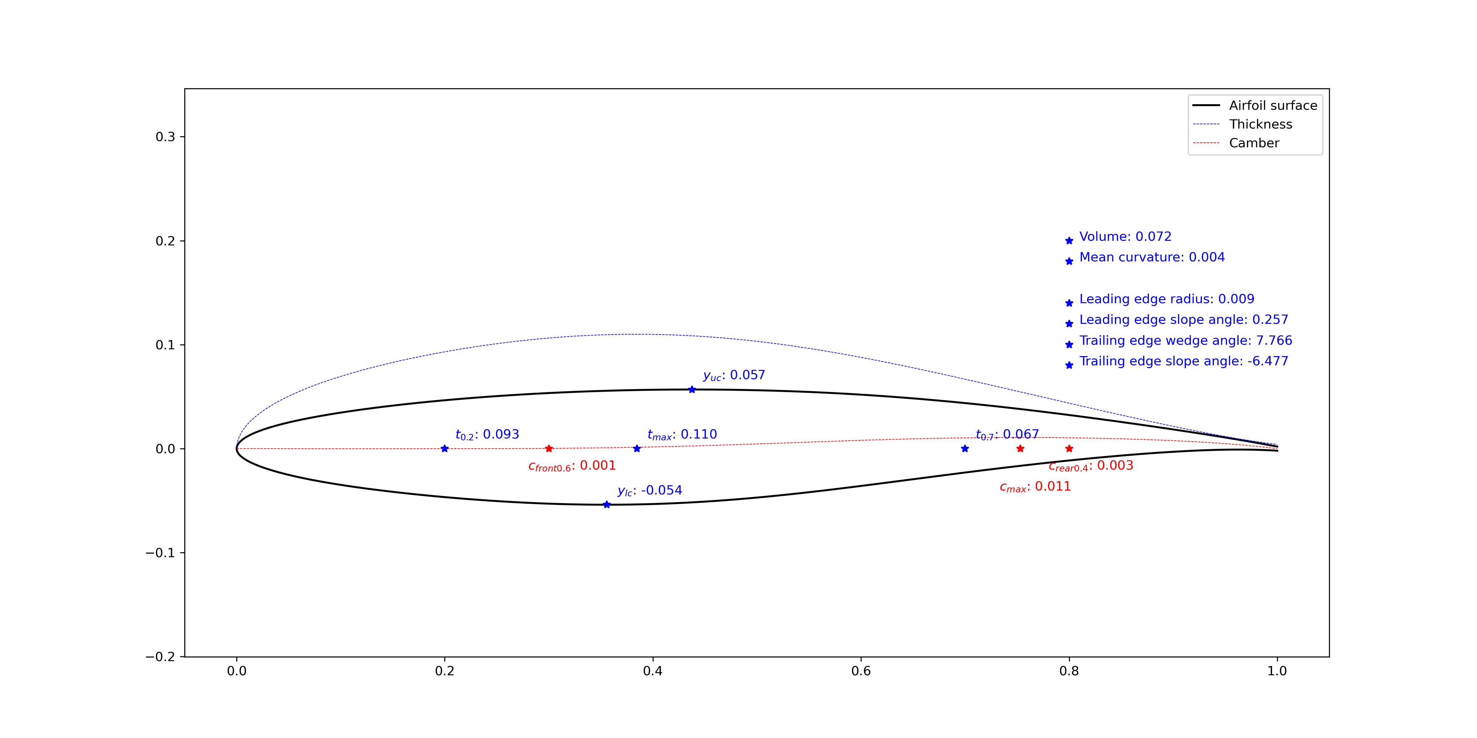
Figure 2.4.2 Airfoil geometric features (tail=0.004)
2.4.2. Geometric modification
The FoilModification class
provides functions to add bumps and incremental curves to airfoil upper and lower surfaces,
or add bumps to the airfoil thickness line or camber line.
The modified geometry will be reconstructed by the CST method with the specified number of CST parameters.
In Figure 2.4.3, a bump centered at \(x=0.30\) are added to the airfoil upper surface, and a bump centered at \(x=0.85\) are added to the airfoil lower surface. When the airfoil maximum thickness is kept the same, the lower surface is affected by adding the bump to the upper surface.
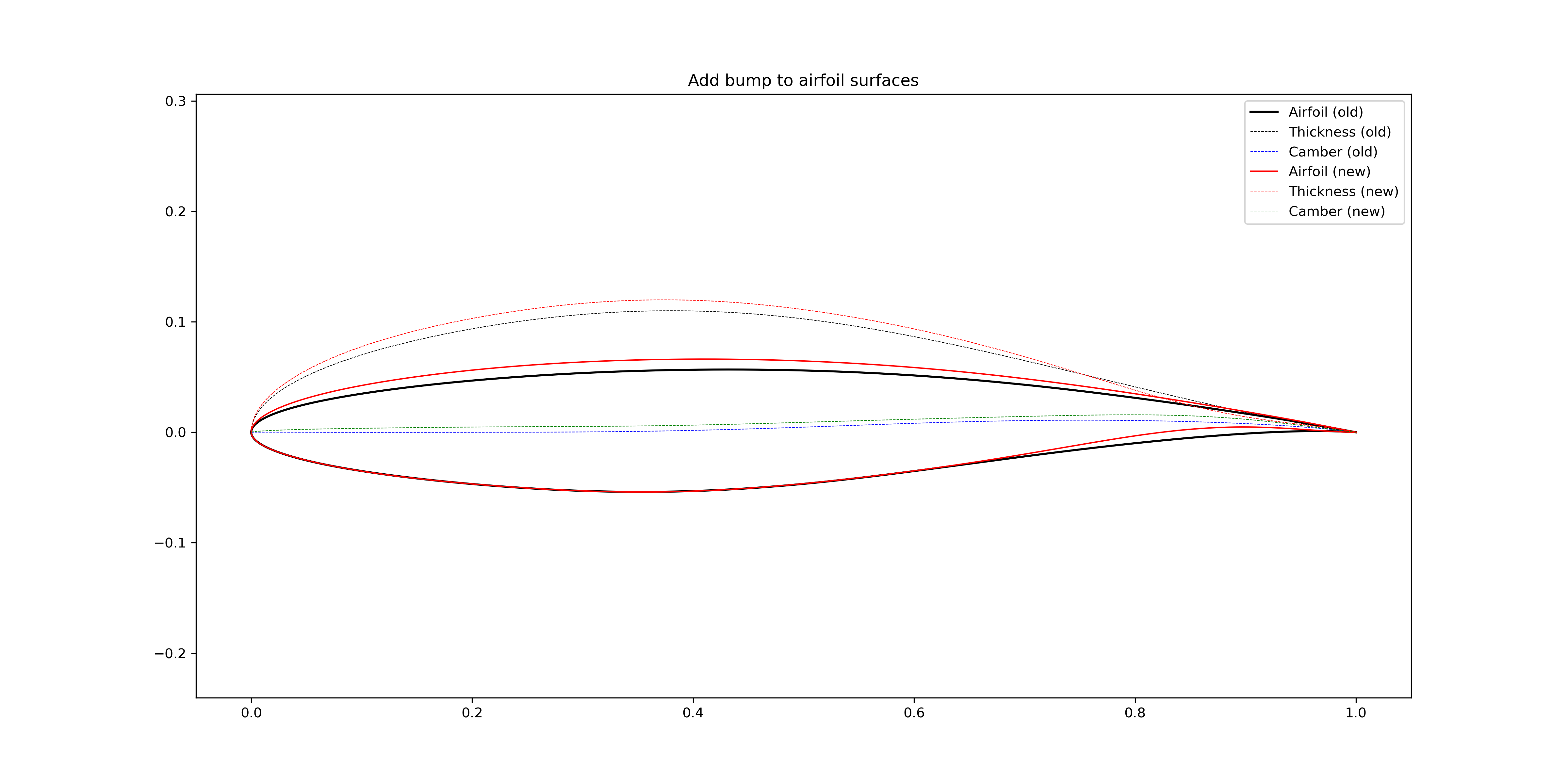
Figure 2.4.3 Add bumps to the airfoil surfaces (not keep the \(t_\text{max}\))
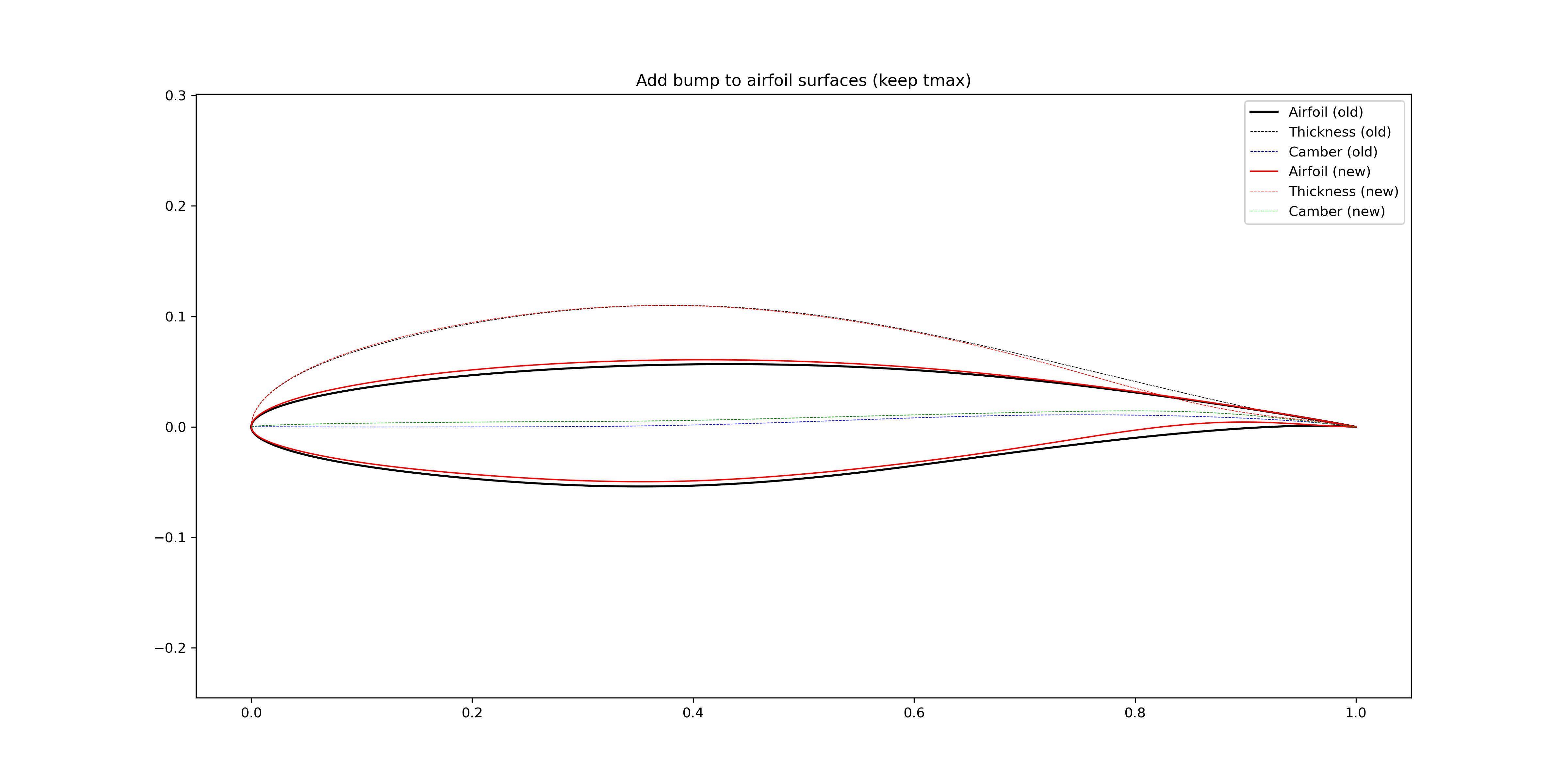
Figure 2.4.4 Add bumps to the airfoil surfaces (keep the \(t_\text{max}\))
In Figure 2.4.5, the airfoil camber is increased in a global sense by adding a bump centered at \(x=0.30\). In Figure 2.4.6, the airfoil camber is increased locally in the aft loading region, a bump centered at \(x=0.80\) is added to the airfoil camber line.
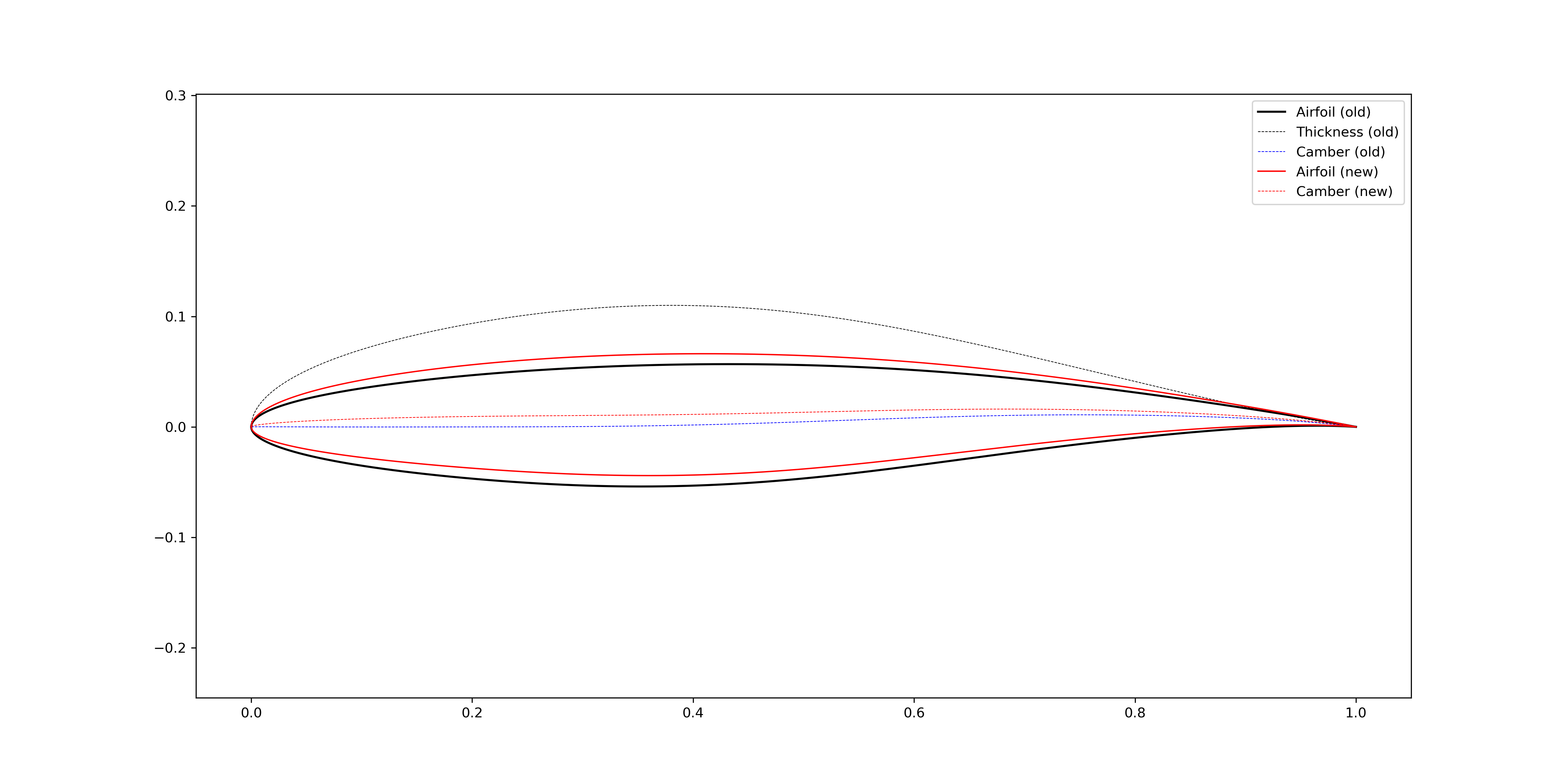
Figure 2.4.5 Increase airfoil camber in a global sense (bump center = 0.3)
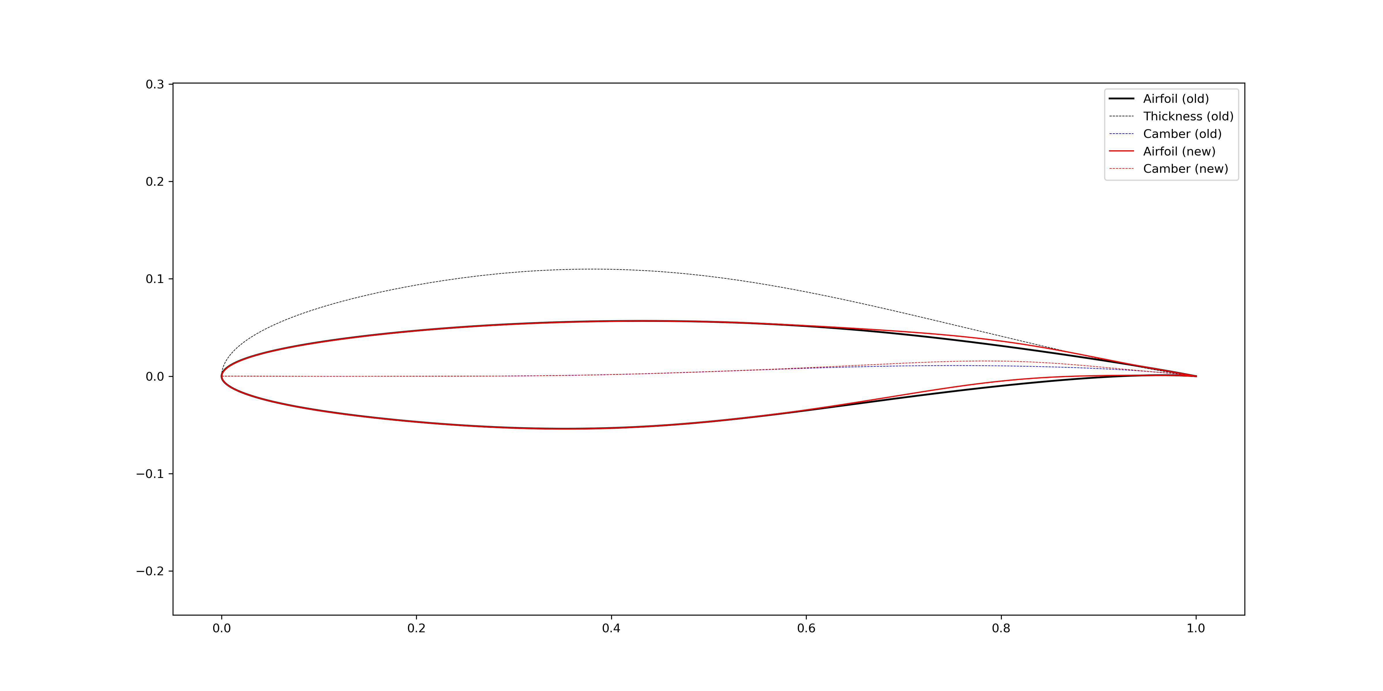
Figure 2.4.6 Increase airfoil camber in the aft loading region (bump center = 0.8)
2.4.3. Leading edge modification
The FoilModification class
provides functions to modify global geometric features of airfoils.
Leading edge radius
In Figure 2.4.7, the airfoil leading edge radius is increased by adding a bump centered at \(x=0.005\) to the airfoil thickness line. Similarly, the radius can be reduced, as shown in Figure 2.4.8.
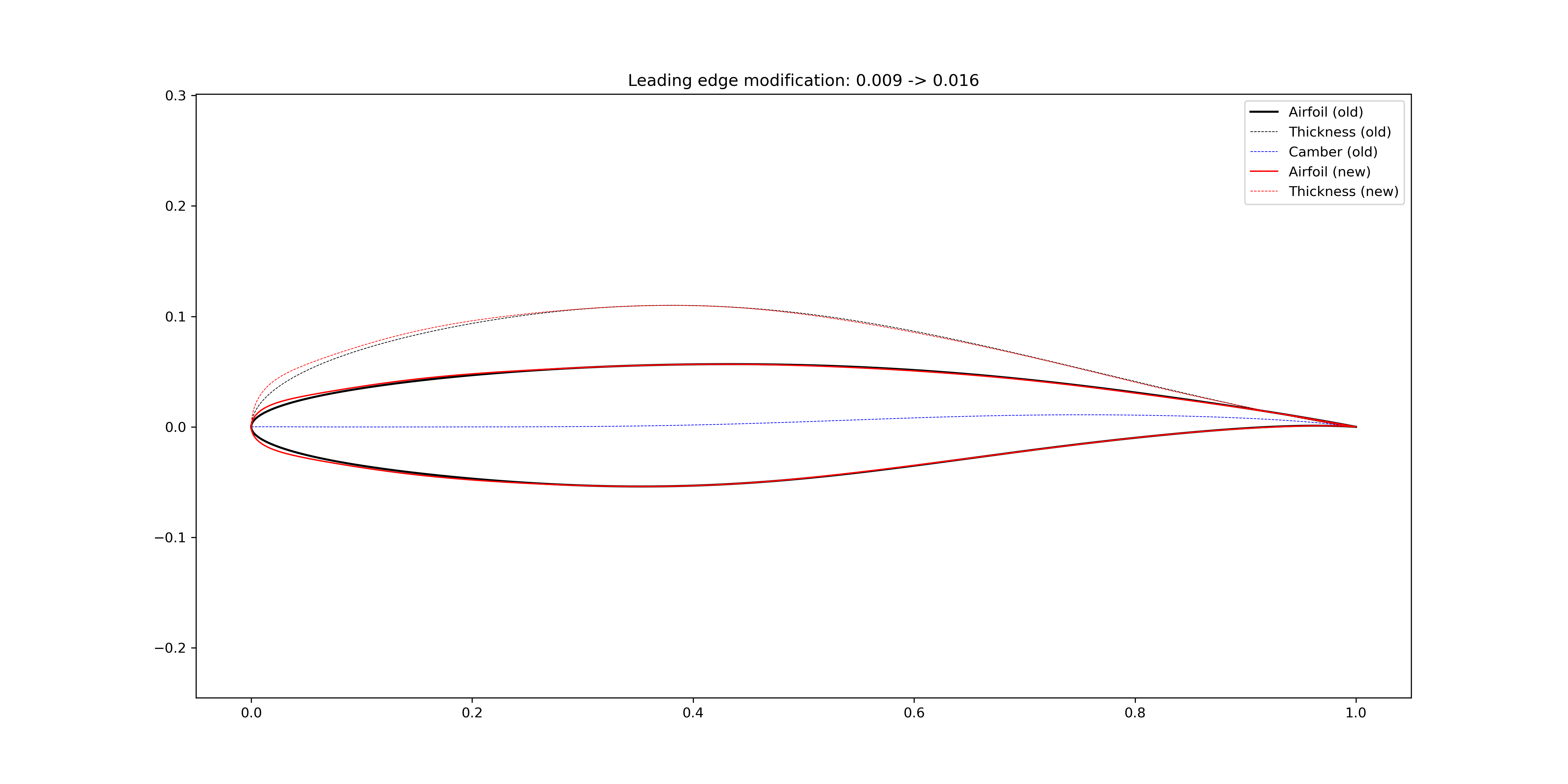
Figure 2.4.7 Increase airfoil leading edge radius
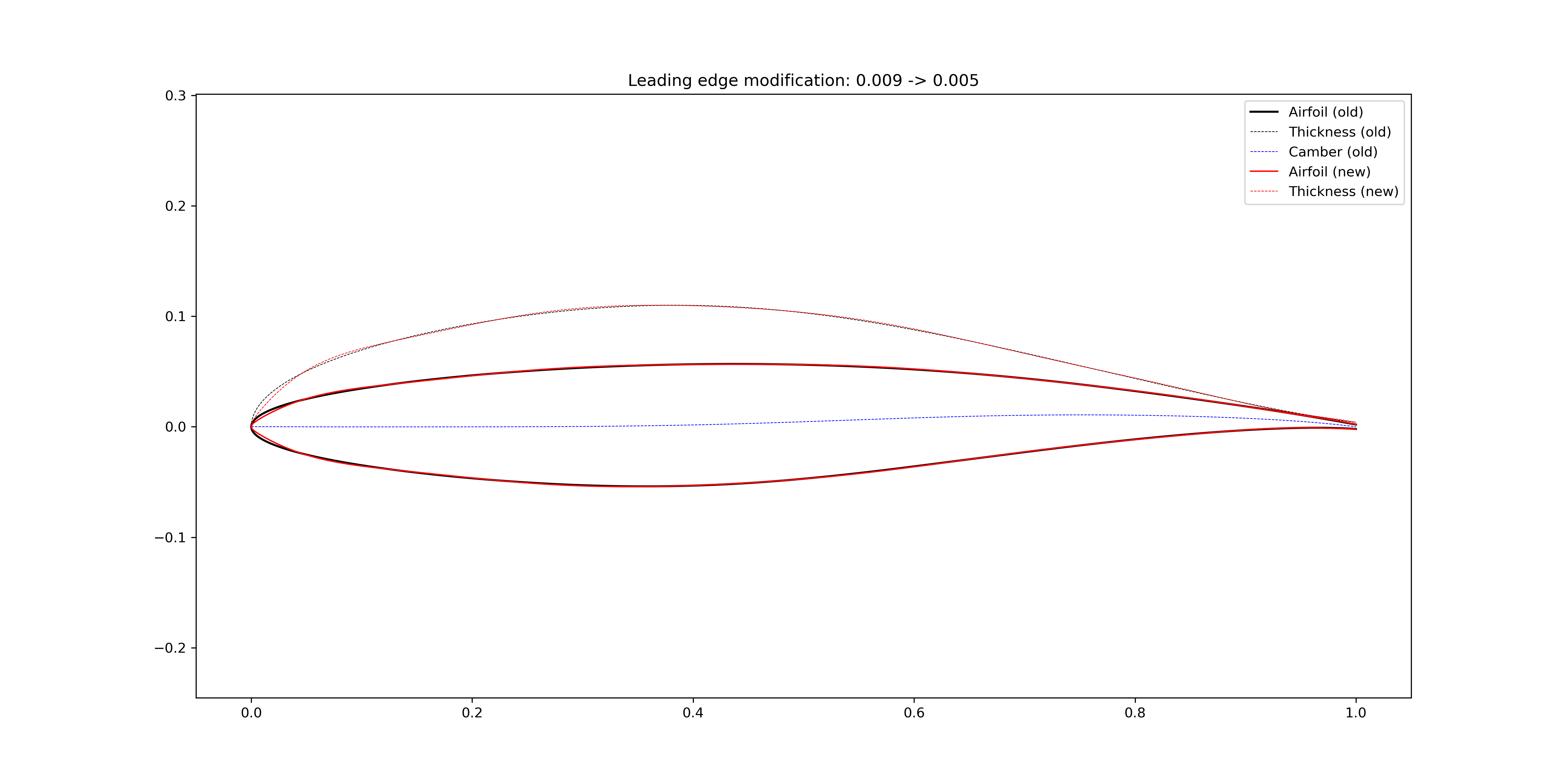
Figure 2.4.8 Reduce airfoil leading edge radius
Leading edge slope angle
In Figure 2.4.9, the airfoil leading edge slope angle is increased by adding a bump centered at \(x=0.05\) to the airfoil camber line. The bump width is 0.6 so that the modification is more locally. In Figure 2.4.10, the bump width is increased to 1.0.
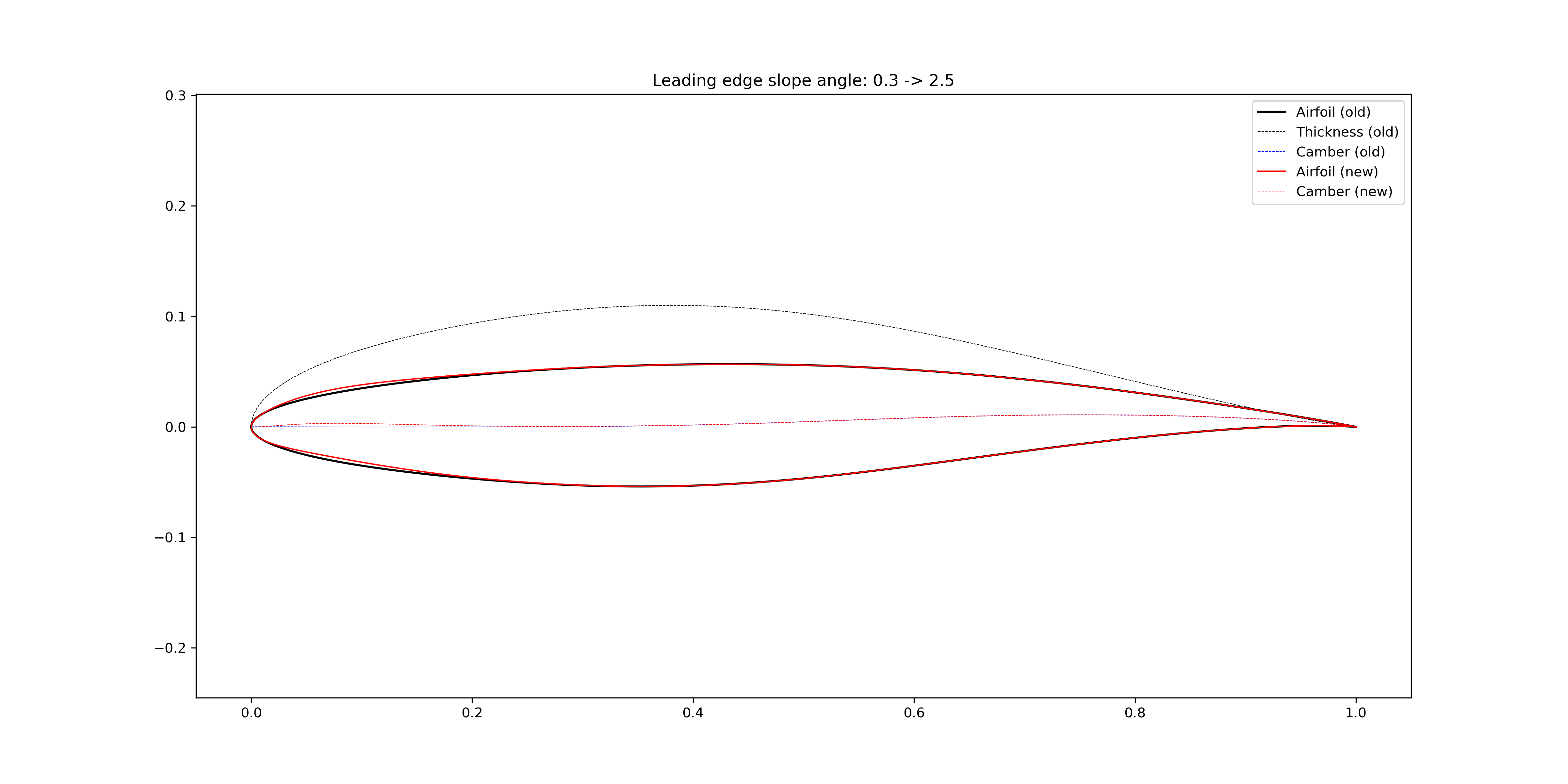
Figure 2.4.9 Increase airfoil leading edge slope angle (bump width = 0.6)
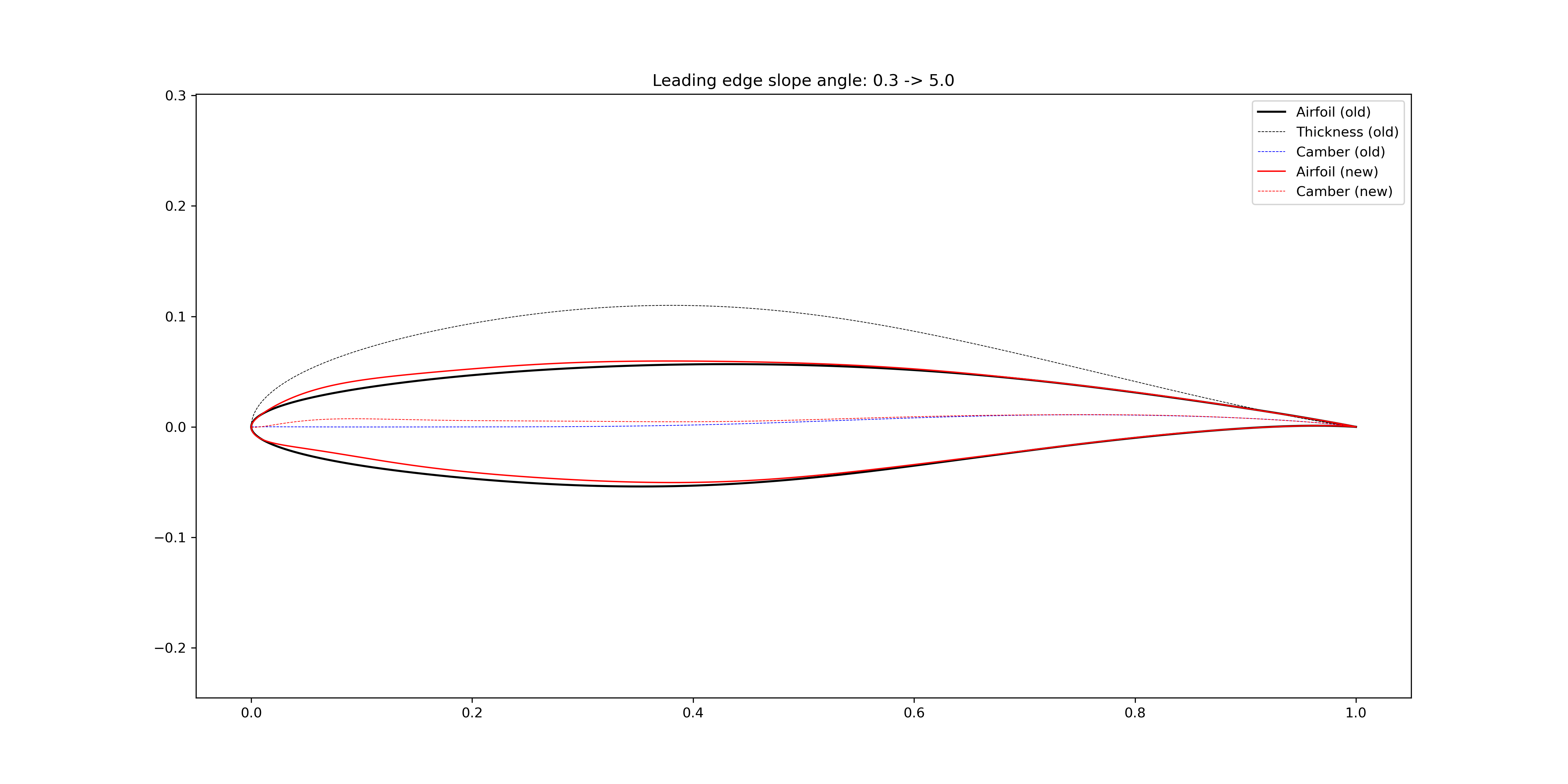
Figure 2.4.10 Increase airfoil leading edge slope angle (bump width = 1.0)
2.4.4. Trailing edge modification
The FoilModification class
provides functions to modify global geometric features of airfoils.
Wedge angle

Figure 2.4.11 Increase airfoil trailing edge wedge angle
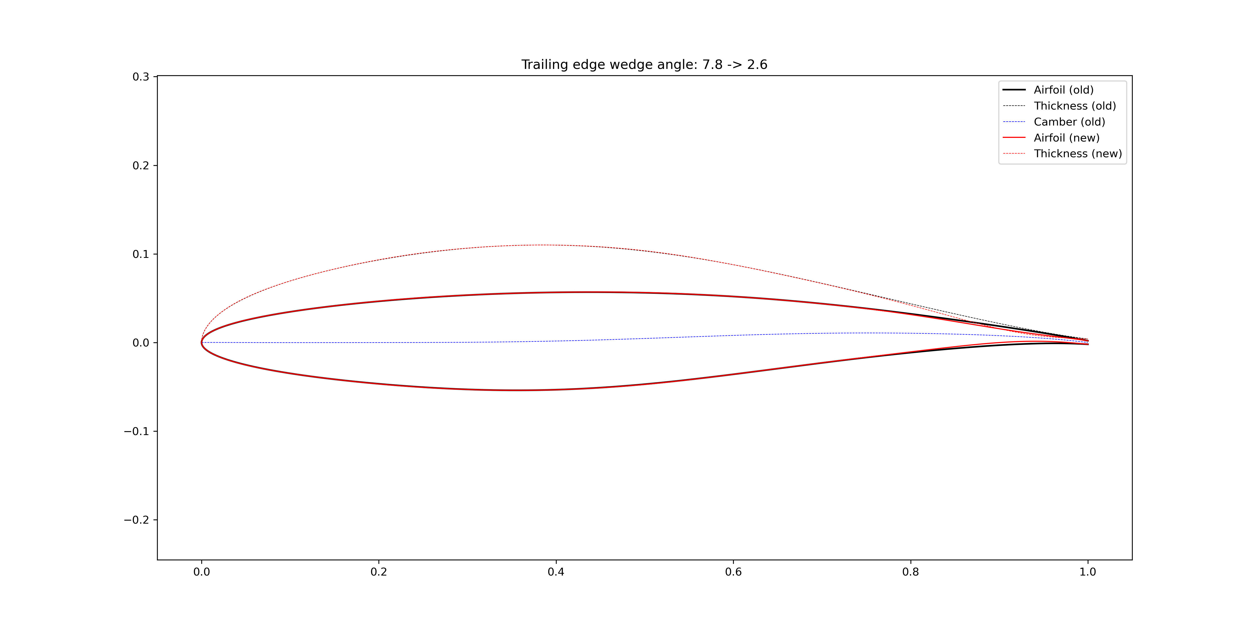
Figure 2.4.12 Reduce airfoil trailing edge wedge angle
Slope angle
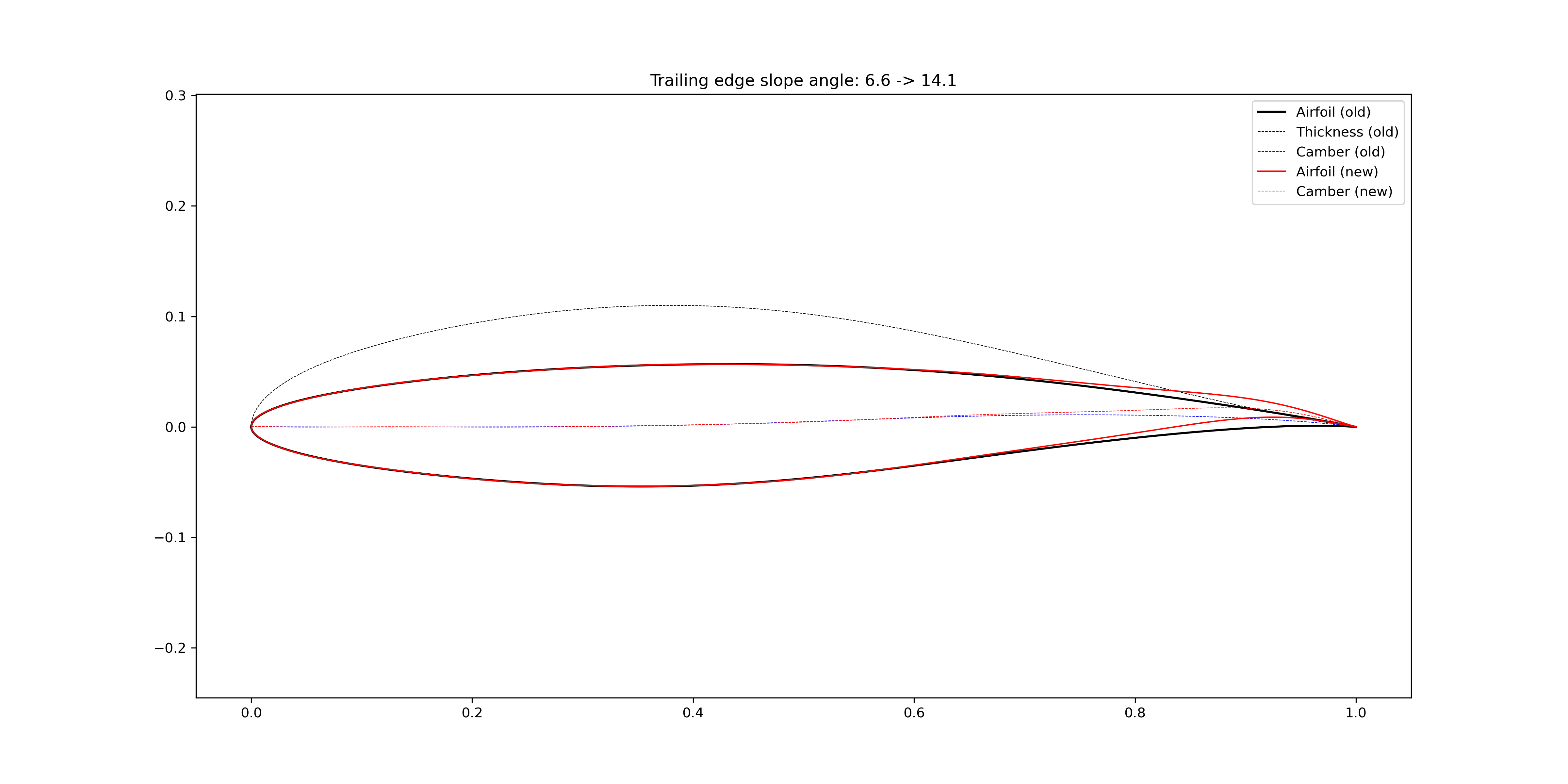
Figure 2.4.13 Increase airfoil trailing edge slope angle
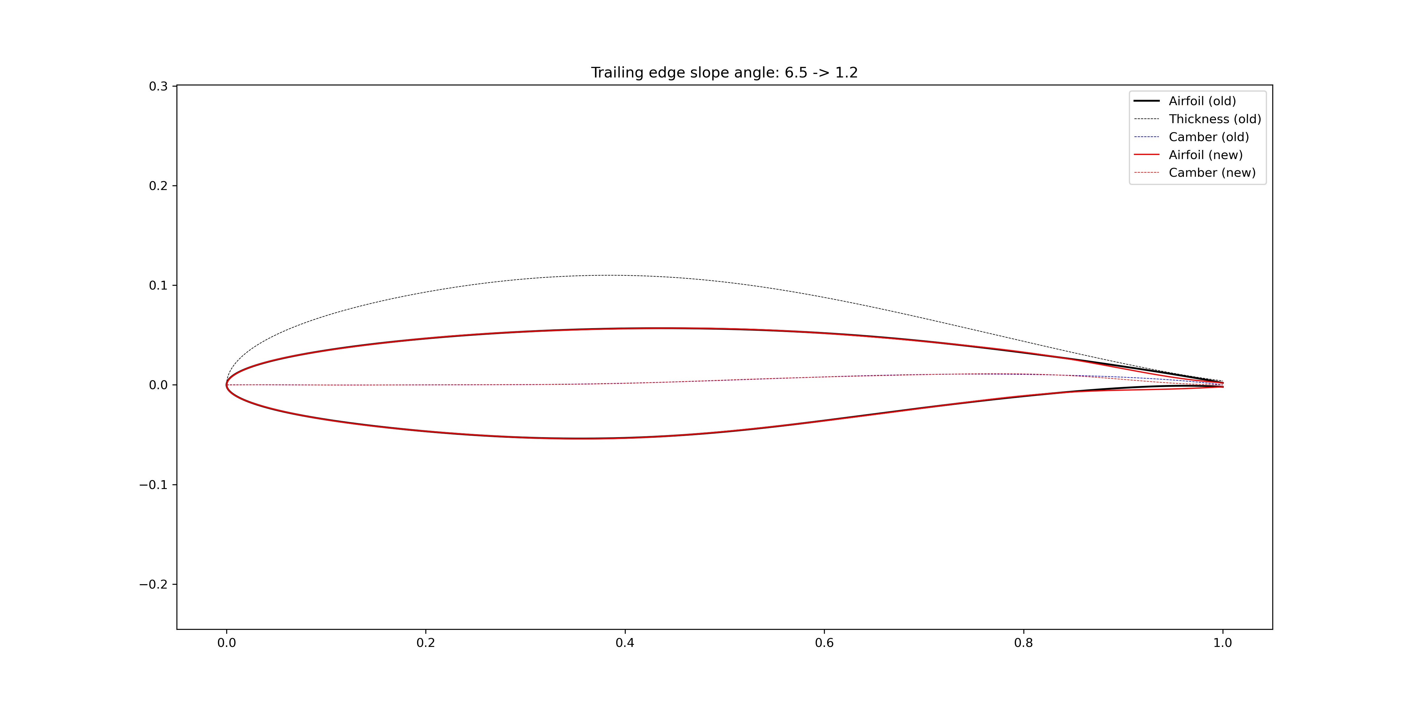
Figure 2.4.14 Reduce airfoil trailing edge slope angle
2.4.5. Maximum thickness location
The FoilModification class
provides functions to modify global geometric features of airfoils.
The maximum location is changed by transforming the x coordinates.
The details can be found in CoordinateTransformation.
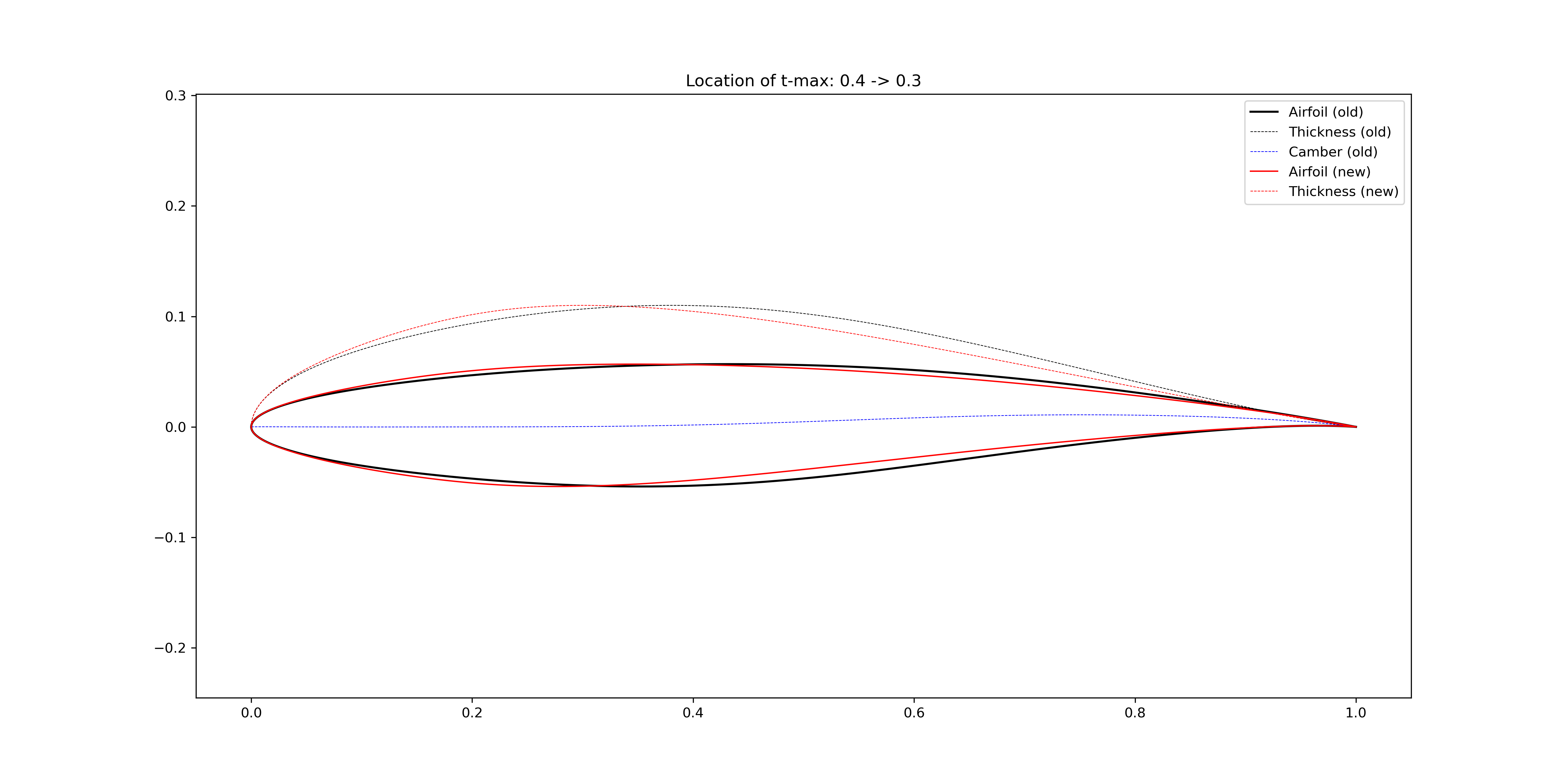
Figure 2.4.15 Transform the airfoil maximum thickness location to 30% chord
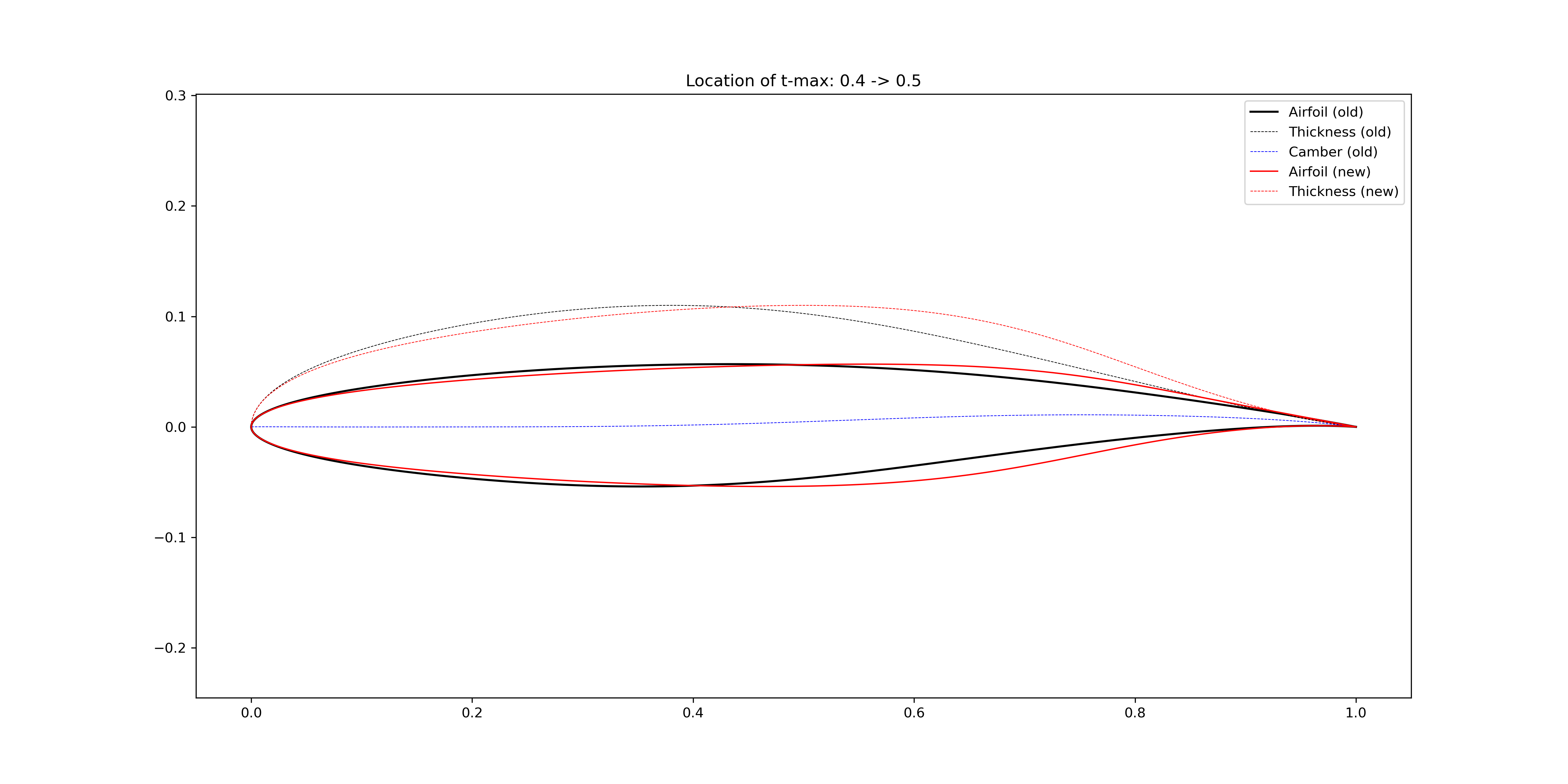
Figure 2.4.16 Transform the airfoil maximum thickness location to 50% chord
2.4.6. Thickness at certain locations
The FoilModification class
provides functions to modify global geometric features of airfoils.
The thickness is modified by adding bumps to the thickness line.
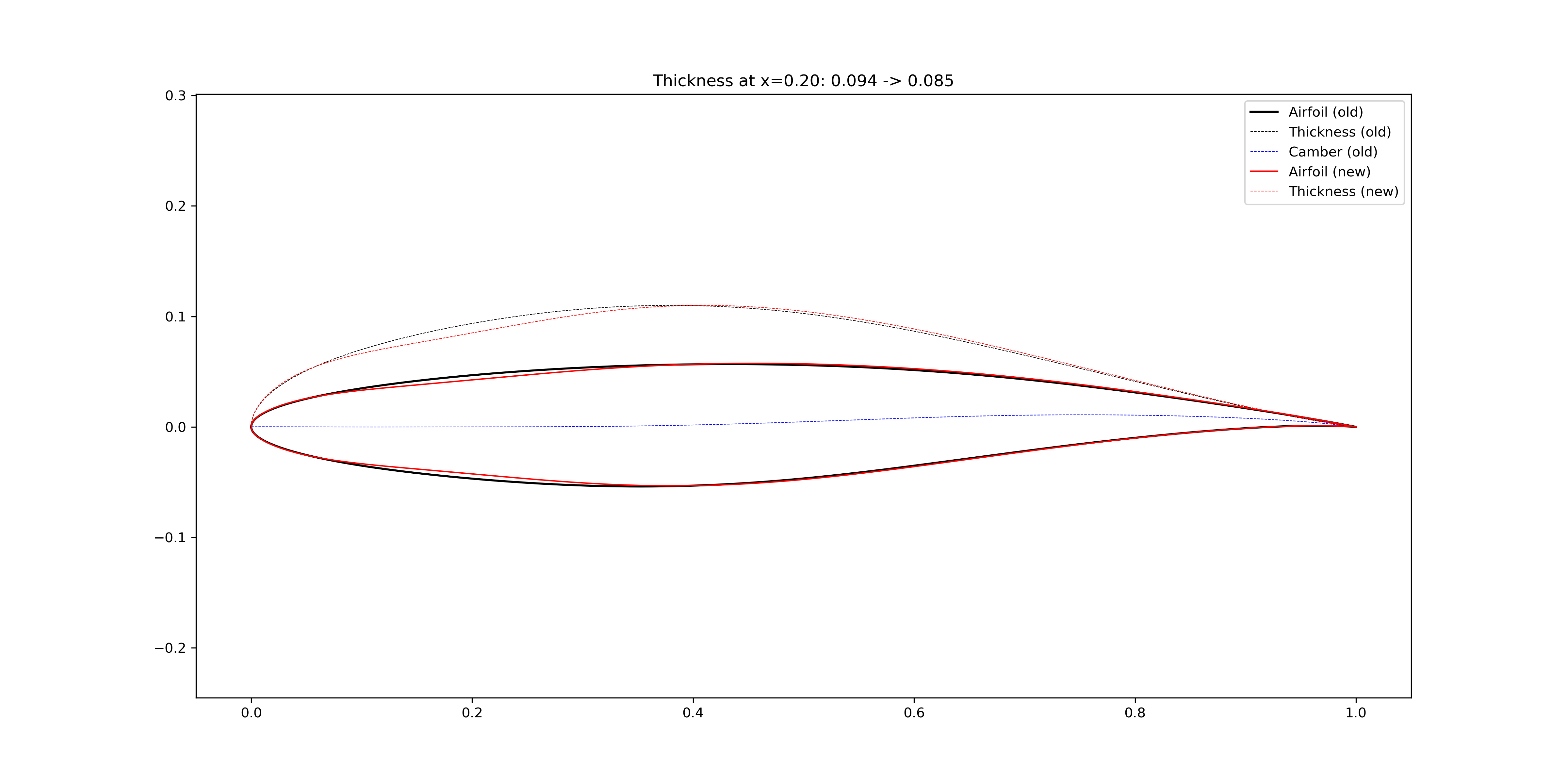
Figure 2.4.17 Change the airfoil thickness at x=0.20
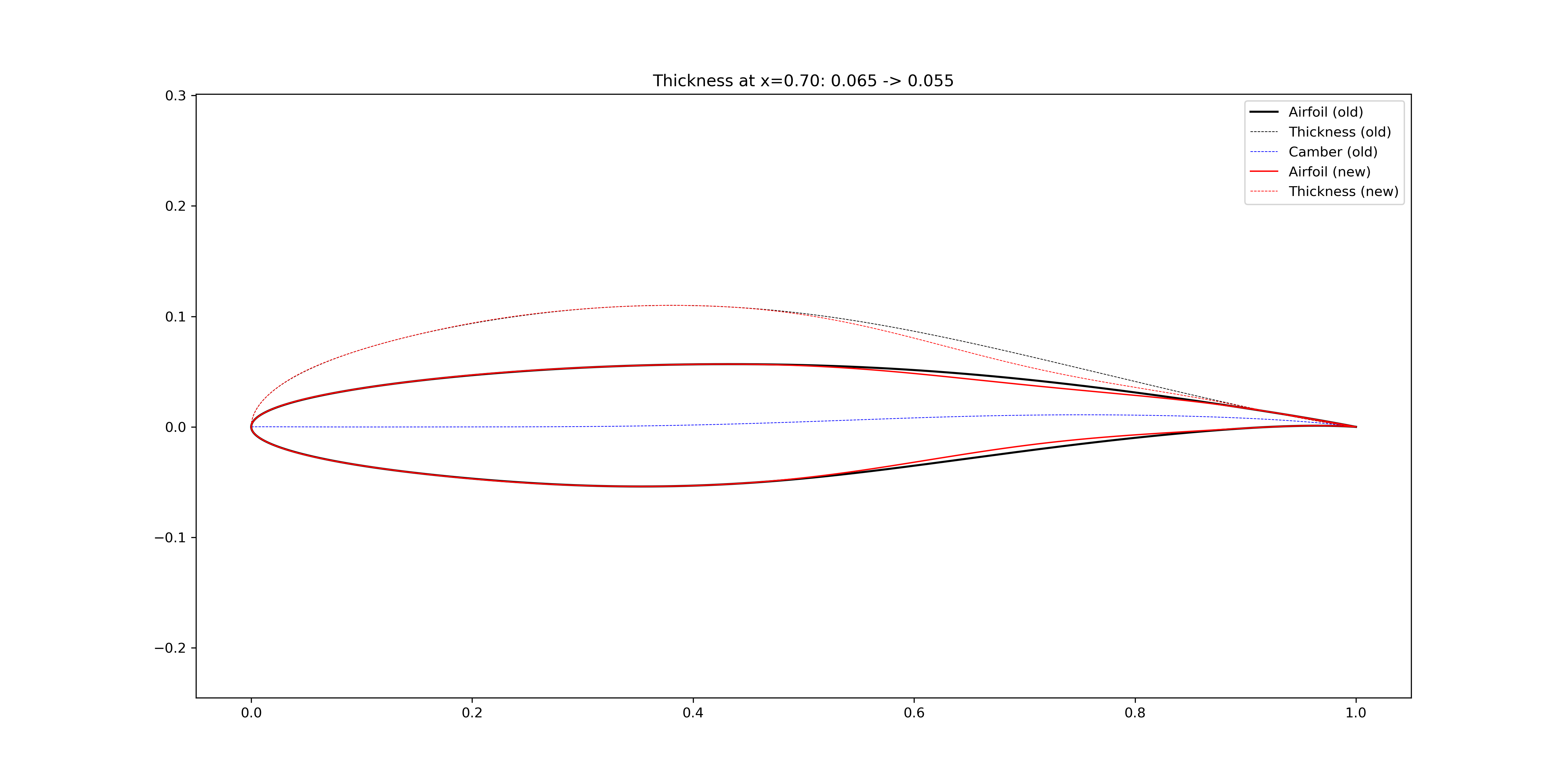
Figure 2.4.18 Change the airfoil thickness at x=0.70
2.4.7. Average camber
The FoilModification class
provides functions to modify global geometric features of airfoils.
The camber is modified by adding bumps to the camber line.
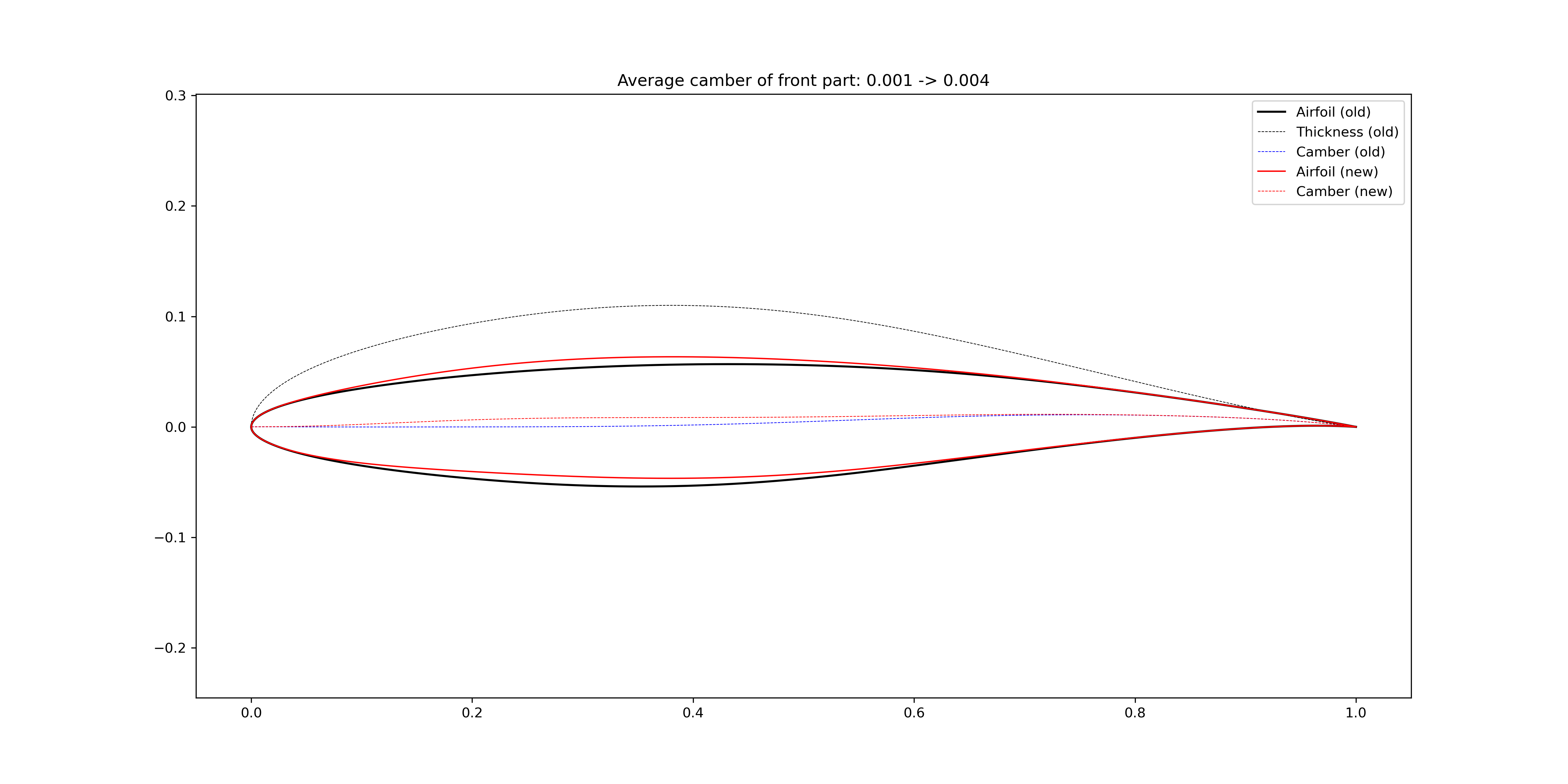
Figure 2.4.19 Change the airfoil average camber of the front 60%
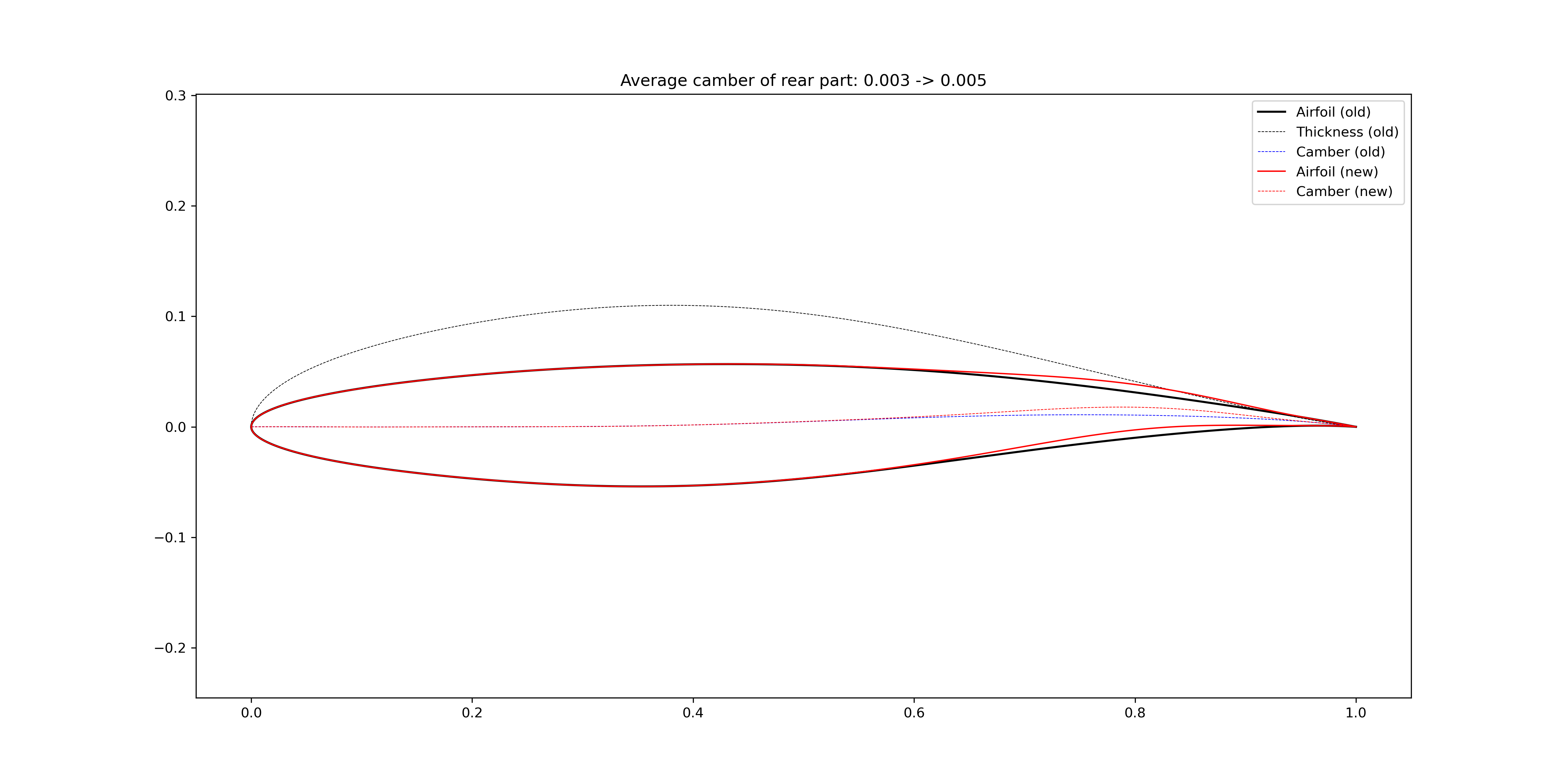
Figure 2.4.20 Change the airfoil average camber of the rear 40%